Product Description
Product Description
MAIN FEATURES:
1) Made of high quality material, non-rusting;Both flange and foot mounting available and suitable for all-round installation
2) Large output torque and high radiating efficiency
3)Precise grinding helical gear with Smooth running and low noise, no deformation,can work long time in dreadful condition
4)Nice appearance, durable service life and small volume, compact structure
5)Both 2 and 3 stage available with wide ratio range from 5 to 200
6)Different output shaft diameter available -40-50mm
7)Modular construction enlarge ratio from 5 to 1400
MAIN MATERIALS:
1)housing with aluminium alloyand cast iron material;
2)Output Shaft Material:20CrMnTi
3)Good quality no noise bearings to keep long service life
4)High performance oil seal to prevent from oil leakage
APPLICATIONS:
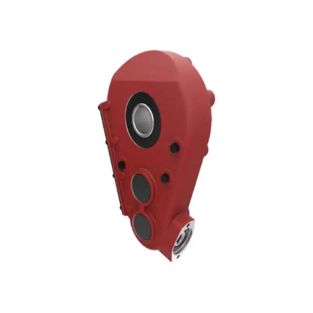
G3 Series helical gear motor are wide used for all kinds of automatic equipment, such as chip removal machine, conveyor, packaging equipment, woodworking machinery, farming equipment, slurry scraper ,dryer, mixer and so on.
Detailed Photos
Product Parameters
| (n1=1400r/min 50hz) | |||||||||||||||||
| norminal ratio | 5 | 10 | 15 | 20 | 25 | 30 | 40 | 50 | 60 | 80 | 100 | 100 | 120 | 160 | 200 | ||
| 0.1kw | output shaft | Ø18 | Ø22 | ||||||||||||||
| n2* (r/min) | 282 | 138 | 92 | 70 | 56 | 46 | 35 | 28 | 23 | 18 | 14 | – | 11 | 9 | 7 | ||
| M2(Nm) | 50hz | 3.2 | 6.5 | 9.8 | 12.9 | 16.1 | 19.6 | 25.7 | 31.1 | 37.5 | 49.5 | 62.9 | – | 76.1 | 100.7 | 125.4 | |
| 60hz | 3 | 5 | 8 | 11 | 13 | 17 | 21 | 26 | 31 | 41 | 52 | – | 63 | 84 | 105 | ||
| Fr1(N) | 588 | 882 | 980 | 1180 | 1270 | 1370 | 1470 | 1570 | 2160 | 2450 | 2450 | 2450 | 2450 | 2450 | 2450 | ||
| Fr2(N) | 176 | ||||||||||||||||
| norminal ratio | 5 | 10 | 15 | 20 | 25 | 30 | 40 | 50 | 60 | 80 | 100 | 100 | 120 | 160 | 200 | ||
| 0.2kw | output shaft | Ø18 | Ø22 | Ø28 | |||||||||||||
| n2* (r/min) | 282 | 138 | 92 | 70 | 56 | 45 | 35 | 29 | 23 | 18 | 14 | 13 | 12 | 8 | 7 | ||
| M2(Nm) | 50hz | 6.5 | 12.6 | 19.1 | 26.3 | 32.6 | 38.9 | 50.4 | 63 | 75.6 | 100.8 | 103.9 | 125.4 | 150 | 200.4 | 250.7 | |
| 60hz | 5.4 | 10.5 | 16.6 | 21.9 | 27.1 | 32.4 | 42 | 52.5 | 63 | 84 | 86.6 | 104.5 | 125 | 167 | 208.9 | ||
| Fr1(N) | 588 | 882 | 980 | 1180 | 1270 | 1760 | 1860 | 1960 | 2160 | 2450 | 2450 | 2840 | 3330 | 3430 | 3430 | ||
| Fr2(N) | 196 | ||||||||||||||||
| norminal ratio | 5 | 10 | 15 | 20 | 25 | 30 | 40 | 50 | 60 | 80 | 100 | 100 | 120 | 160 | 200 | ||
| 0.4kw | output shaft | Ø22 | Ø28 | Ø32 | |||||||||||||
| n2* (r/min) | 288 | 144 | 92 | 72 | 58 | 47 | 36 | 29 | 24 | 18 | 14 | 14 | 12 | 9 | 7 | ||
| M2(Nm) | 50hz | 12.9 | 25 | 38.6 | 51.4 | 65.4 | 78.2 | 100.7 | 125.4 | 150 | 200.4 | 206.8 | 250.7 | 301.1 | 400.7 | 461.8 | |
| 60hz | 10.7 | 20.8 | 32.1 | 42.9 | 54.5 | 65.2 | 83.9 | 104.5 | 125 | 167 | 172.3 | 208.9 | 250.9 | 333.9 | 384.8 | ||
| Fr1(N) | 882 | 1180 | 1370 | 1470 | 1670 | 2550 | 2840 | 3140 | 3430 | 3430 | 3430 | 4900 | 5880 | 5880 | 5880 | ||
| Fr2(N) | 245 | ||||||||||||||||
| norminal ratio | 5 | 10 | 15 | 20 | 25 | 30 | 40 | 50 | 60 | 80 | 100 | 100 | 120 | 160 | 200 | ||
| 0.75kw | output shaft | Ø28 | Ø32 | Ø40 | |||||||||||||
| n2* (r/min) | 278 | 140 | 94 | 69 | 58 | 46 | 35 | 29 | 24 | 18 | 14 | 14 | 11 | 9 | 7 | ||
| M2(Nm) | 50hz | 24.6 | 48.2 | 72.9 | 97.5 | 122.1 | 145.7 | 187.5 | 235.7 | 282.9 | 376.1 | 387.9 | 439 | 527 | 703 | 764 | |
| 60hz | 20.5 | 40.2 | 60.7 | 81.3 | 201.8 | 121.4 | 156.3 | 196.4 | 235.7 | 313.4 | 323.2 | 366 | 439 | 585 | 732 | ||
| Fr1(N) | 1270 | 1760 | 2160 | 2350 | 2450 | 4571 | 4210 | 4610 | 5490 | 5880 | 5880 | 7060 | 7060 | 7060 | 7060 | ||
| Fr2(N) | 294 | ||||||||||||||||
| norminal ratio | 5 | 10 | 15 | 20 | 25 | 30 | 40 | 50 | 60 | 80 | 100 | 100 | 120 | 160 | 200 | ||
| 1.5kw | output shaft | Ø32 | Ø40 | Ø50 | |||||||||||||
| n2* (r/min) | 280 | 140 | 93 | 70 | 55 | 47 | 34 | 27 | 24 | 17 | 14 | 13 | 12 | 8 | 7 | ||
| M2(Nm) | 50hz | 48.2 | 97.5 | 145.7 | 193.9 | 242.1 | 272 | 351 | 439 | 527 | 703 | 724 | 878 | 1060 | 1230 | 1230 | |
| 60hz | 40.2 | 81.3 | 121.4 | 161.6 | 201.8 | 226 | 293 | 366 | 439 | 585 | 603 | 732 | 878 | 1170 | 1230 | ||
| Fr1(N) | 1760 | 2450 | 2840 | 3230 | 3820 | 5100 | 5880 | 7060 | 7060 | 7060 | 7060 | 9800 | 9800 | 9800 | 9800 | ||
| Fr2(N) | 343 | ||||||||||||||||
| norminal ratio | 5 | 10 | 15 | 20 | 25 | 30 | 40 | 50 | 60 | 80 | 100 | ||||||
| 2.2kw | output shaft | Ø40 | Ø50 | ||||||||||||||
| n2* (r/min) | 272 | 136 | 95 | 68 | 54 | 45 | 36 | 28 | 24 | 18 | 14 | ||||||
| M2(Nm) | 50hz | 67 | 133 | 200 | 266 | 332 | 399 | 515 | 644 | 773 | 1571 | 1230 | |||||
| 60hz | 56 | 111 | 167 | 221 | 277 | 332 | 429 | 537 | 644 | 858 | 1080 | ||||||
| Fr1(N) | 2160 | 3140 | 3530 | 4571 | 4700 | 6960 | 7250 | 8620 | 9800 | 9800 | 9800 | ||||||
| Fr2(N) | 392 | ||||||||||||||||
Outline and mounting dimension:
| G3FM: THREE PHASE GEAR MOTOR WITH FLANGE (n1=1400r/min) | ||||||||||||||||||||
| Power kw | output shaft | ratio | A | F | I | J | M | O | O1 | P | Q | R | S | T | U | W | X | Y | Y1 | |
| standard | brake | |||||||||||||||||||
| 0.1kw | Ø18 | 5–30-40-50 | 236 | 270 | 192.5 | 11 | 16.5 | 170 | 4 | 10 | 30 | 145 | 35 | 18 | 20.5 | 129 | 6 | 157 | 80 | 81 |
| Ø22 | -160-200 | 262 | 296 | 197.5 | 11 | 19 | 185 | 4 | 12 | 40 | 148 | 47 | 22 | 24.5 | 129 | 6 | 171.5 | 89.5 | 83.5 | |
| 0.2kw | Ø18 | 5- | 267 | 270 | 192.5 | 11 | 16.5 | 170 | 4 | 10 | 30 | 145 | 35 | 18 | 20.5 | 129 | 6 | 161 | 80 | 81 |
| Ø22 | -80-100 | 293 | 296 | 197.5 | 11 | 19 | 185 | 4 | 12 | 40 | 148 | 47 | 22 | 24.5 | 129 | 6 | 171.5 | 89.5 | 83.5 | |
| Ø28 | 306 | 309.5 | 208.5 | 11 | 23.5 | 215 | 4 | 15 | 45 | 170 | 50 | 28 | 31 | 129 | 8 | 198.5 | 105.5 | 88 | ||
| 0.4kw | Ø22 | 5- | 314 | 324.5 | 204 | 11 | 19 | 185 | 4 | 12 | 40 | 148 | 47 | 22 | 24.5 | 139 | 6 | 171.5 | 89.5 | 88.5 |
| Ø28 | -80-100 | 330 | 337.5 | 215 | 11 | 23.5 | 215 | 4 | 15 | 45 | 170 | 50 | 28 | 31 | 139 | 8 | 198.5 | 105.5 | 93 | |
| Ø32 | 349 | 357 | 229.5 | 13 | 28.5 | 250 | 4 | 15 | 55 | 180 | 60 | 32 | 35 | 139 | 10 | 234 | 126 | 98 | ||
| 0.75kw | Ø28 | 5- | 350.5 | 343.5 | 227.5 | 11 | 23.5 | 215 | 4 | 15 | 45 | 170 | 50 | 28 | 31 | 159 | 8 | 198.5 | 105.5 | 103 |
| Ø32 | -80-100 | 379.5 | 387 | 242 | 13 | 28.5 | 250 | 4 | 15 | 55 | 180 | 60 | 32 | 35 | 159 | 10 | 234 | 126 | 108 | |
| Ø40 | 401.5 | 408.5 | 270 | 18 | 34 | 310 | 5 | 18 | 65 | 230 | 71 | 40 | 43 | 185 | 12 | 284 | 149 | 126.5 | ||
| 1.5kw | Ø32 | 5- | 420.5 | 441 | 254 | 13 | 28.5 | 250 | 5 | 15 | 55 | 180 | 60 | 32 | 35 | 185 | 10 | 234 | 126 | 121 |
| Ø40 | -80-100 | 457.5 | 478 | 270 | 18 | 34 | 310 | 5 | 18 | 65 | 230 | 71 | 40 | 43 | 185 | 12 | 284 | 149 | 126.5 | |
| Ø50 | 485.5 | 506 | 300 | 22 | 40 | 360 | 5 | 25 | 75 | 270 | 83 | 50 | 53.5 | 185 | 14 | 325 | 173.5 | 132.5 | ||
| 2.2kw | Ø40 | 5- | 466.5 | 487 | 270 | 18 | 34 | 310 | 5 | 18 | 65 | 230 | 71 | 40 | 43 | 185 | 12 | 284 | 149 | 126.5 |
| Ø50 | -80-100 | 510.5 | 531 | 300 | 22 | 40 | 360 | 5 | 25 | 75 | 270 | 83 | 50 | 53.5 | 185 | 14 | 325 | 173.5 | 132.5 | |
| G3LM: THREE PHASE GEAR MOTOR WITH FOOT (n1=1400r/min) | ||||||||||||||||||||
| Power kw | output shaft | ratio | A | D | E | F | J | G | H | K | P | S | T | U | V | W | X | Y | Y1 | |
| standard | brake | |||||||||||||||||||
| 0.1kw | Ø18 | 5–30-40-50 | 236 | 270 | 40 | 110 | 135 | 16.5 | 65 | 9 | 45 | 30 | 18 | 20.5 | 129 | 183 | 6 | 133 | 85 | 10 |
| Ø22 | -160-200 | 262 | 296 | 65 | 130 | 155 | 19 | 90 | 11 | 55 | 40 | 22 | 24.5 | 129 | 193 | 6 | 139.5 | 90 | 12 | |
| 0.2kw | Ø18 | 5- | 267 | 270 | 40 | 110 | 135 | 16.5 | 65 | 9 | 45 | 30 | 18 | 20.5 | 129 | 183 | 6 | 133 | 85 | 10 |
| Ø22 | -80-100 | 293 | 296 | 65 | 130 | 155 | 19 | 90 | 11 | 55 | 40 | 22 | 24.5 | 129 | 193 | 6 | 139.5 | 90 | 12 | |
| Ø28 | 306 | 309.5 | 90 | 140 | 175 | 23.5 | 125 | 11 | 65 | 45 | 28 | 31 | 129 | 203 | 8 | 170 | 110 | 15 | ||
| 0.4kw | Ø22 | 5- | 314 | 324.5 | 65 | 130 | 155 | 19 | 90 | 11 | 55 | 40 | 22 | 24.5 | 139 | 199.5 | 6 | 141.5 | 90 | 12 |
| Ø28 | -80-100 | 330 | 337.5 | 90 | 140 | 175 | 23.5 | 125 | 11 | 65 | 45 | 28 | 31 | 139 | 210 | 8 | 170 | 110 | 15 | |
| Ø32 | 349 | 357 | 130 | 170 | 208 | 28.5 | 170 | 13 | 70 | 55 | 32 | 35 | 139 | 226 | 10 | 198 | 130 | 18 | ||
| 0.75kw | Ø28 | 5- | 350.5 | 343.5 | 90 | 140 | 175 | 23.5 | 125 | 11 | 65 | 45 | 28 | 31 | 159 | 222 | 8 | 170 | 110 | 15 |
| Ø32 | -80-100 | 379.5 | 387 | 130 | 170 | 208 | 28.5 | 170 | 13 | 70 | 55 | 32 | 35 | 159 | 238.5 | 10 | 198 | 130 | 18 | |
| Ø40 | 401.5 | 408.5 | 150 | 210 | 254 | 34 | 196 | 15 | 90 | 65 | 40 | 43 | 185 | 249 | 12 | 230 | 150 | 20 | ||
| 1.5kw | Ø32 | 5- | 420.5 | 441 | 130 | 170 | 208 | 28.5 | 170 | 13 | 70 | 55 | 32 | 35 | 185 | 250.5 | 10 | 198 | 130 | 18 |
| Ø40 | -80-100 | 457.5 | 478 | 150 | 210 | 254 | 34 | 196 | 15 | 90 | 65 | 40 | 43 | 185 | 260 | 12 | 230 | 150 | 20 | |
| Ø50 | 485.5 | 506 | 160 | 230 | 290 | 40 | 210 | 18 | 100 | 75 | 50 | 53.5 | 185 | 288 | 14 | 265 | 170 | 25 | ||
| 2.2kw | Ø40 | 5- | 466.5 | 487 | 150 | 210 | 254 | 34 | 196 | 15 | 90 | 65 | 40 | 43 | 185 | 260 | 12 | 230 | 150 | 20 |
| Ø50 | -80-100 | 510.5 | 531 | 160 | 230 | 290 | 40 | 210 | 18 | 100 | 75 | 50 | 53.5 | 185 | 288 | 14 | 265 | 170 | 25 | |
| G3FS: IEC GEAR REDUCER WITH FOOT (n1=1400r/min) | |||||||||||||||||||||||||
| Power kw | output shaft | ratio | A | B | C | F | I | J | L | M | N | O | O1 | P | Q | R | S | S1 | T | T1 | W | W1 | X | Y | Y1 |
| 0.12kw | Ø18 | 5–30-40-50 | 147 | 95 | 115 | 154 | 11 | 16.5 | 4.5 | 170 | 140 | 4 | 10 | 30 | 145 | 35 | 18 | 11 | 20.5 | 12.8 | 6 | 4 | 163 | 80 | 86.5 |
| Ø22 | -160-200 | 173 | 95 | 115 | 164 | 11 | 19 | 4.5 | 185 | 140 | 4 | 12 | 40 | 148 | 47 | 22 | 11 | 24.5 | 12.8 | 6 | 4 | 171.5 | 89.5 | 89 | |
| 0.18kw | Ø18 | 5- | 147 | 95 | 115 | 154 | 11 | 16.5 | 4.5 | 170 | 140 | 4 | 10 | 30 | 145 | 35 | 18 | 11 | 20.5 | 12.8 | 6 | 4 | 163 | 80 | 86.5 |
| Ø22 | -80-100 | 173 | 95 | 115 | 164 | 11 | 19 | 4.5 | 185 | 140 | 4 | 12 | 40 | 148 | 47 | 22 | 11 | 24.5 | 12.8 | 6 | 4 | 171.5 | 89.5 | 89 | |
| Ø28 | 186.5 | 95 | 115 | 186 | 11 | 23.5 | 4.5 | 215 | 140 | 4 | 15 | 45 | 170 | 50 | 28 | 11 | 31 | 12.8 | 8 | 4 | 198.5 | 105.5 | 93.5 | ||
| 0.37kw | Ø22 | 5- | 181.5 | 110 | 130 | 164 | 11 | 19 | 4.5 | 185 | 160 | 4 | 12 | 40 | 148 | 47 | 22 | 14 | 24.5 | 16.3 | 6 | 5 | 201 | 89.5 | 99 |
| Ø28 | -80-100 | 198 | 110 | 130 | 186 | 11 | 23.5 | 4.5 | 215 | 160 | 4 | 15 | 45 | 170 | 50 | 28 | 14 | 31 | 16.3 | 8 | 5 | 198.5 | 105.5 | 103.5 | |
| Ø32 | 216.5 | 110 | 130 | 215 | 13 | 28.5 | 4.5 | 250 | 160 | 4 | 15 | 55 | 180 | 60 | 32 | 14 | 35 | 16.3 | 10 | 5 | 234 | 126 | 108.5 | ||
| 0.75kw | Ø28 | 5- | 206.5 | 130 | 165 | 185 | 11 | 23.5 | 4.5 | 215 | 200 | 4 | 15 | 45 | 170 | 50 | 28 | 19 | 31 | 21.8 | 8 | 6 | 216.5 | 105.5 | 123.5 |
| Ø32 | -80-100 | 235 | 130 | 165 | 215 | 13 | 28.5 | 4.5 | 250 | 200 | 4 | 15 | 55 | 180 | 60 | 32 | 19 | 35 | 21.8 | 10 | 6 | 236.5 | 126 | 128.5 | |
| Ø40 | 260.5 | 130 | 165 | 270 | 18 | 34 | 4.5 | 310 | 200 | 5 | 18 | 65 | 230 | 71 | 40 | 19 | 43 | 21.8 | 12 | 8 | 284 | 149 | 134 | ||
| 1.5kw | Ø32 | 5- | 252 | 130 | 165 | 215 | 13 | 28.5 | 4.5 | 250 | 200 | 5 | 15 | 55 | 180 | 60 | 32 | 24 | 35 | 27.3 | 10 | 8 | 236.5 | 126 | 128.5 |
| Ø40 | -80-100 | 293.5 | 130 | 165 | 270 | 18 | 34 | 4.5 | 310 | 200 | 5 | 18 | 65 | 230 | 71 | 40 | 24 | 43 | 27.3 | 12 | 8 | 284 | 149 | 134 | |
| Ø50 | 321.5 | 130 | 165 | 300 | 22 | 40 | 4.5 | 360 | 200 | 5 | 25 | 75 | 270 | 83 | 50 | 24 | 53.5 | 27.3 | 14 | 8 | 323.5 | 173.5 | 140 | ||
| 2.2kw | Ø40 | 5- | 290 | 180 | 215 | 270 | 18 | 34 | 5.5 | 310 | 250 | 5 | 18 | 65 | 230 | 71 | 40 | 28 | 43 | 31.3 | 12 | 8 | 284 | 149 | 134 |
| Ø50 | -80-100 | 334 | 180 | 215 | 300 | 22 | 40 | 5.5 | 360 | 250 | 5 | 25 | 75 | 270 | 83 | 50 | 28 | 53.5 | 31.3 | 14 | 8 | 323.5 | 173.5 | 140 | |
| G3LS: IEC GEAR REDUCER WITH FOOT (n1=1400r/min) | |||||||||||||||||||||||||
| Power kw | output shaft | ratio | A | B | C | D | E | F | G | H | J | K | L | N | P | S | S1 | T | T1 | W | W1 | X | Y | Y1 | Z |
| 0.12kw | Ø18 | 5–30-40-50 | 147 | 95 | 115 | 40 | 110 | 135 | 65 | 9 | 16.5 | 45 | 4.5 | 140 | 30 | 18 | 11 | 20.5 | 12.8 | 6 | 4 | 138.5 | 85 | 10 | M8 |
| Ø22 | -160-200 | 173 | 95 | 115 | 65 | 130 | 154 | 90 | 11 | 19 | 55 | 4.5 | 140 | 40 | 22 | 11 | 24.5 | 12.8 | 6 | 4 | 141 | 90 | 12 | M8 | |
| 0.18kw | Ø18 | 5- | 147 | 95 | 115 | 40 | 110 | 135 | 65 | 9 | 16.5 | 45 | 4.5 | 140 | 30 | 18 | 11 | 20.5 | 12.8 | 6 | 4 | 138.5 | 85 | 10 | M8 |
| Ø22 | -80-100 | 173 | 95 | 115 | 65 | 130 | 154 | 90 | 11 | 19 | 55 | 4.5 | 140 | 40 | 22 | 11 | 24.5 | 12.8 | 6 | 4 | 141 | 90 | 12 | M8 | |
| Ø28 | 186.5 | 95 | 115 | 90 | 140 | 175 | 125 | 11 | 23.5 | 65 | 4.5 | 140 | 45 | 28 | 11 | 31 | 12.8 | 8 | 4 | 170 | 110 | 15 | M8 | ||
| 0.37kw | Ø22 | 5- | 181.5 | 110 | 130 | 65 | 130 | 154 | 90 | 11 | 19 | 55 | 4.5 | 160 | 40 | 22 | 14 | 24.5 | 16.3 | 6 | 5 | 151 | 90 | 12 | M8 |
| Ø28 | -80-100 | 198 | 110 | 130 | 90 | 140 | 175 | 125 | 11 | 23.5 | 65 | 4.5 | 160 | 45 | 28 | 14 | 31 | 16.3 | 8 | 5 | 170 | 110 | 15 | M8 | |
| Ø32 | 216.5 | 110 | 130 | 130 | 170 | 208 | 170 | 13 | 28.5 | 70 | 4.5 | 160 | 55 | 32 | 14 | 35 | 16.3 | 10 | 5 | 198 | 130 | 18 | M8 | ||
| 0.75kw | Ø28 | 5- | 206.5 | 130 | 165 | 90 | 140 | 175 | 125 | 11 | 23.5 | 65 | 4.5 | 200 | 45 | 28 | 19 | 31 | 21.8 | 8 | 6 | 186.5 | 110 | 15 | M10 |
| Ø32 | -80-100 | 235 | 130 | 165 | 130 | 170 | 208 | 170 | 13 | 28.5 | 70 | 4.5 | 200 | 55 | 32 | 19 | 35 | 21.8 | 10 | 6 | 201.5 | 130 | 18 | M10 | |
| Ø40 | 260.5 | 130 | 165 | 150 | 210 | 254 | 196 | 15 | 34 | 90 | 4.5 | 200 | 65 | 40 | 19 | 43 | 21.8 | 12 | 8 | 230 | 150 | 20 | M10 | ||
| 1.5kw | Ø32 | 5- | 252 | 130 | 165 | 130 | 170 | 208 | 170 | 13 | 28.5 | 70 | 4.5 | 200 | 55 | 32 | 24 | 35 | 27.3 | 10 | 8 | 201.5 | 130 | 18 | M10 |
| Ø40 | -80-100 | 293.5 | 130 | 165 | 150 | 210 | 254 | 196 | 15 | 34 | 90 | 4.5 | 200 | 65 | 40 | 24 | 43 | 27.3 | 12 | 8 | 230 | 150 | 20 | M10 | |
| Ø50 | 321.5 | 130 | 165 | 160 | 230 | 290 | 210 | 18 | 40 | 100 | 4.5 | 200 | 75 | 50 | 24 | 53.5 | 27.3 | 14 | 8 | 265 | 170 | 25 | M10 | ||
| 2.2kw | Ø40 | 5- | 290 | 180 | 215 | 150 | 210 | 254 | 196 | 15 | 34 | 90 | 5.5 | 250 | 65 | 40 | 28 | 43 | 31.3 | 12 | 8 | 230 | 150 | 20 | M12 |
| Ø50 | -80-100 | 334 | 180 | 215 | 160 | 230 | 290 | 210 | 18 | 40 | 100 | 5.5 | 250 | 75 | 50 | 28 | 53.5 | 31.3 | 14 | 8 | 265 | 170 | 25 | M12 | |
Company Profile
We are a professional reducer manufacturer located in HangZhou, ZHangZhoug province.Our leading products is full range of RV571-150 worm reducers , also supplied GKM hypoid helical gearbox, GRC inline helical gearbox, PC units, UDL Variators and AC Motors, G3 helical gear motor.Products are widely used for applications such as: foodstuffs, ceramics, packing, chemicals, pharmacy, plastics, paper-making, construction machinery, metallurgic mine, environmental protection engineering, and all kinds of automatic lines, and assembly lines.With fast delivery, superior after-sales service, advanced producing facility, our products sell well both at home and abroad. We have exported our reducers to Southeast Asia, Eastern Europe and the Middle East and so on.Our aim is to develop and innovate on the basis of high quality, and create a good reputation for reducers.
Workshop:
Exhibition
ZheJiang PTC Fair:
Packaging & Shipping
After Sales Service
1.Maintenance Time and Warranty:Within 1 year after receiving goods.
2.Other Service: Including modeling selection guide, installation guide, and problem resolution guide, etc
FAQ
1.Q:Can you make as per customer drawing?
A: Yes, we offer customized service for customers accordingly. We can use customer’s nameplate for gearboxes.
2.Q:What is your terms of payment ?
A: 30% deposit before production,balance T/T before delivery.
3.Q:Are you a trading company or manufacturer?
A:We are a manufacurer with advanced equipment and experienced workers.
4.Q:What’s your production capacity?
A:4000-5000 PCS/MONTH
5.Q:Free sample is available or not?
A:Yes, we can supply free sample if customer agree to pay for the courier cost
6.Q:Do you have any certificate?
A:Yes, we have CE certificate and SGS certificate report.
Contact information:
Ms Lingel Pan
For any questions just feel free ton contact me. Many thanks for your kind attention to our company!
| Application: | Motor, Machinery, Marine, Agricultural Machinery, Power Transmission Applications |
|---|---|
| Function: | Distribution Power, Clutch, Change Drive Torque, Change Drive Direction, Speed Changing, Speed Reduction |
| Layout: | Coaxial |
| Hardness: | Hardened Tooth Surface |
| Installation: | Vertical or Horizontal Type |
| Step: | Two Stage- Three Stage |
| Samples: |
US$ 35/Piece
1 Piece(Min.Order) | |
|---|
| Customization: |
Available
| Customized Request |
|---|
Technological Advancements in Agricultural Gearbox Design
Advancements in agricultural gearbox design have significantly improved the efficiency, durability, and performance of farming equipment. Here are some notable technological advancements:
- Materials and Manufacturing: The use of advanced materials, such as high-strength alloys and composite materials, has enhanced the durability and longevity of gearbox components. Precision manufacturing techniques, including computer-aided design (CAD) and computer numerical control (CNC) machining, ensure tight tolerances and reliable performance.
- Gear Tooth Design: Modern gear tooth profiles, such as optimized helical and spiral bevel gears, reduce noise, vibration, and wear. Advanced tooth design also improves power transmission efficiency and load distribution.
- Sealing and Lubrication: Improved sealing technologies, such as double-lip seals and labyrinth seals, help prevent contaminants from entering gearboxes while retaining lubricants. Advanced lubrication systems, including automatic lubrication and improved oil formulations, extend maintenance intervals and enhance efficiency.
- Electronic Controls: Agricultural gearboxes increasingly integrate with electronic control systems. Sensors and actuators provide real-time data on gearbox performance, allowing for condition monitoring, predictive maintenance, and adjustments to optimize machinery operation.
- Smart Gearboxes: Some agricultural gearboxes are equipped with smart features, such as load sensors, temperature monitors, and feedback systems. These features enhance precision, safety, and overall equipment performance.
- Hybrid Power Transmission: Integration of hybrid power transmission systems, combining internal combustion engines with electric motors, allows for more efficient power delivery and reduced fuel consumption. Gearboxes play a crucial role in managing power distribution in these systems.
- Reduced Environmental Impact: Advancements in gear design contribute to reducing environmental impact. Quieter and more efficient gearboxes minimize noise pollution and energy consumption while meeting emissions regulations.
- Customization and Modularity: Some modern agricultural gearboxes offer modular designs that allow farmers to customize gear ratios, output speeds, and other specifications to match specific tasks and conditions.
- Simulation and Testing: Computer simulations and advanced testing methods, such as finite element analysis (FEA) and computational fluid dynamics (CFD), help optimize gearbox design, reduce prototyping costs, and ensure reliability before production.
These advancements collectively contribute to the evolution of agricultural gearboxes, making farming machinery more efficient, environmentally friendly, and adaptable to the changing needs of modern agriculture.
Potential Challenges in Maintenance and Repairs of Agricultural Gearboxes
Maintenance and repairs of gearboxes in agriculture can pose several challenges:
- Harsh Environments: Agricultural machinery operates in challenging environments with exposure to dirt, debris, moisture, and varying temperatures. These conditions can accelerate wear and corrosion, necessitating frequent maintenance.
- Heavy Workloads: Gearboxes in farming equipment often handle heavy workloads, leading to increased stress on components. This can result in faster wear and tear, requiring more frequent inspections and part replacements.
- Accessibility: Some gearboxes are located in hard-to-reach areas of machinery. This makes regular maintenance and repairs more challenging, as technicians may need specialized tools and equipment to access and service the gearboxes.
- Specialized Knowledge: Proper maintenance of agricultural gearboxes requires specialized knowledge and skills. Inadequate understanding of gearbox mechanics and maintenance practices can lead to improper repairs, reducing the gearbox’s lifespan and efficiency.
- Costs: Repairing or replacing gearbox components can be costly, especially for heavy-duty agricultural machinery. Farmers need to consider both the direct costs of parts and labor, as well as potential downtime during repair processes.
- Downtime: The downtime required for gearbox maintenance or repairs can impact farming operations, especially during critical planting or harvesting seasons. Efficient scheduling and backup equipment can help mitigate this challenge.
- Availability of Parts: Obtaining replacement parts for older or less common gearbox models can be challenging. Farmers may need to source parts from specialized suppliers, leading to potential delays in repairs.
Addressing these challenges requires proactive maintenance planning, regular inspections, proper training of maintenance personnel, and sourcing spare parts in advance.
Maintenance Requirements for Agricultural Gearboxes
Maintaining agricultural gearboxes is crucial to ensure the smooth and efficient operation of farming equipment. Proper maintenance helps extend the lifespan of gearboxes and prevents costly breakdowns. Here are the key maintenance requirements:
- Regular Inspections: Conduct routine visual inspections to check for signs of wear, damage, leaks, or misalignment. Regularly inspect gear teeth, seals, and bearings for any issues.
- Lubrication: Proper lubrication is essential to minimize friction and wear in gearboxes. Follow the manufacturer’s guidelines for the type of lubricant to use and the recommended intervals for lubrication.
- Lubricant Checks: Monitor the gearbox’s lubricant levels and quality regularly. Replace or replenish lubricants as needed, and ensure that contaminants are kept out of the lubrication system.
- Tightening Bolts and Fasteners: Check and tighten bolts, nuts, and fasteners to prevent loosening due to vibrations during operation. Loose components can lead to misalignment and premature wear.
- Seal Inspection: Examine seals for leaks and proper sealing. Damaged or worn seals should be replaced promptly to prevent lubricant leakage and the ingress of contaminants.
- Cleaning: Keep gearboxes clean by removing dirt, debris, and residue. Regular cleaning prevents abrasive particles from entering the gearbox and causing damage.
- Alignment: Ensure that gearboxes are properly aligned with connected components, such as shafts and couplings. Misalignment can lead to increased wear and reduced efficiency.
- Temperature Monitoring: Monitor the operating temperature of the gearbox. Abnormal temperature increases may indicate issues like overloading or insufficient lubrication.
- Filter Replacement: If the gearbox has a filtration system, regularly replace or clean the filters to prevent contaminants from entering the gearbox.
- Expert Inspection: Periodically have gearboxes inspected by qualified technicians. They can identify potential problems that may not be visible during routine inspections.
Adhering to these maintenance requirements ensures that agricultural gearboxes remain in optimal condition and contribute to the reliability and efficiency of farming equipment. Regular maintenance not only prevents unexpected downtime but also prolongs the service life of the gearboxes, ultimately benefiting the productivity of agricultural operations.


editor by CX 2023-11-27